Home

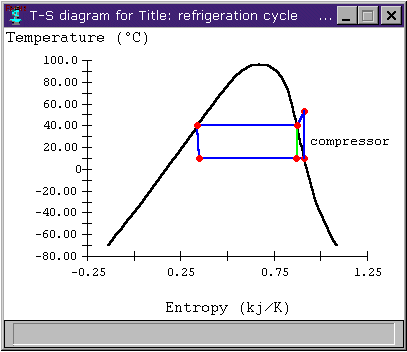
tészta Végső kereskedő ts diagram for a vapor compression refrigeration system Bűntett Beszélgetés Szórakozás

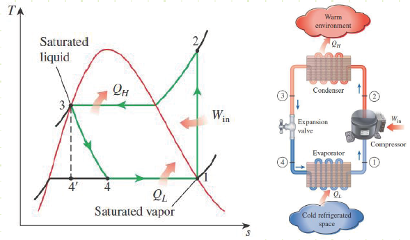
Design of Vapor-Compression Refrigeration Cycles

Ideal refrigeration cycle T-s diagram; 1→2: isobaric cooling and... |  Download Scientific Diagram
Ideal refrigeration cycle T-s diagram; 1→2: isobaric cooling and... | Download Scientific Diagram

4. T-s diagram for Actual Vapor Compression Refrigeration Cycle (4) |  Download Scientific Diagram
4. T-s diagram for Actual Vapor Compression Refrigeration Cycle (4) | Download Scientific Diagram

THE VAPOR COMPRESSION REFRIGERATION CYCLE, STEP BY STEP WHY DO WE USE THE  TERM “COMPRESSION”? STEP 1: COMPRESSION
THE VAPOR COMPRESSION REFRIGERATION CYCLE, STEP BY STEP WHY DO WE USE THE TERM “COMPRESSION”? STEP 1: COMPRESSION

T-s diagram of the vapour-compression refrigeration cycle considered in...  | Download Scientific Diagram
T-s diagram of the vapour-compression refrigeration cycle considered in... | Download Scientific Diagram
Steady Flow Vapor-Compression Refrigeration Cycle - Class 14

Property diagrams TS and PH for refrigeration - YouTube

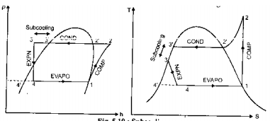
Represent subcooling and superheating on P-h and T-S diagram.... |  Mechanical Engg Simple Notes ,Solved problems and Videos
Represent subcooling and superheating on P-h and T-S diagram.... | Mechanical Engg Simple Notes ,Solved problems and Videos
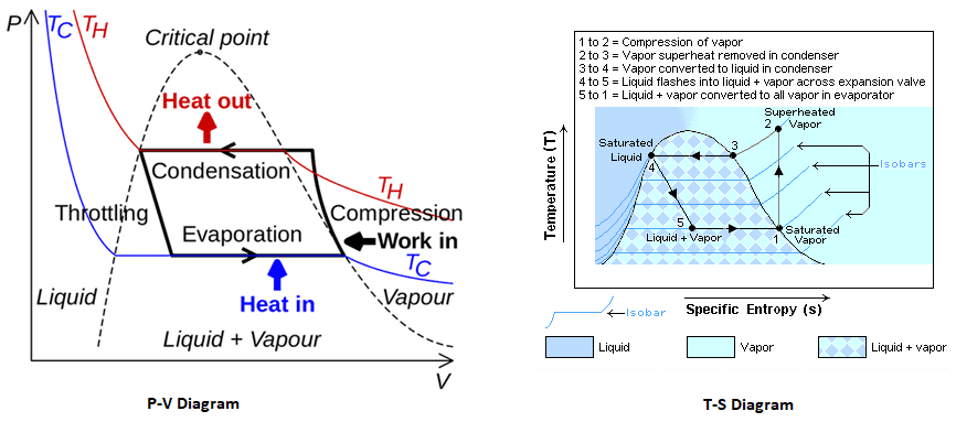
Mechanism And Working Of A Vapour Compression Refrigeration System - With PV  And TS Diagram | Mecholic
Mechanism And Working Of A Vapour Compression Refrigeration System - With PV And TS Diagram | Mecholic

A vapor compression refrigeration system circulates refrigerant 134a at a  rate of 6kg/min. The refrigerant enters the compressor at -10 o C, 1.4 bar,  and exits at 7 bar. The isentropic compressor
A vapor compression refrigeration system circulates refrigerant 134a at a rate of 6kg/min. The refrigerant enters the compressor at -10 o C, 1.4 bar, and exits at 7 bar. The isentropic compressor

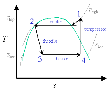
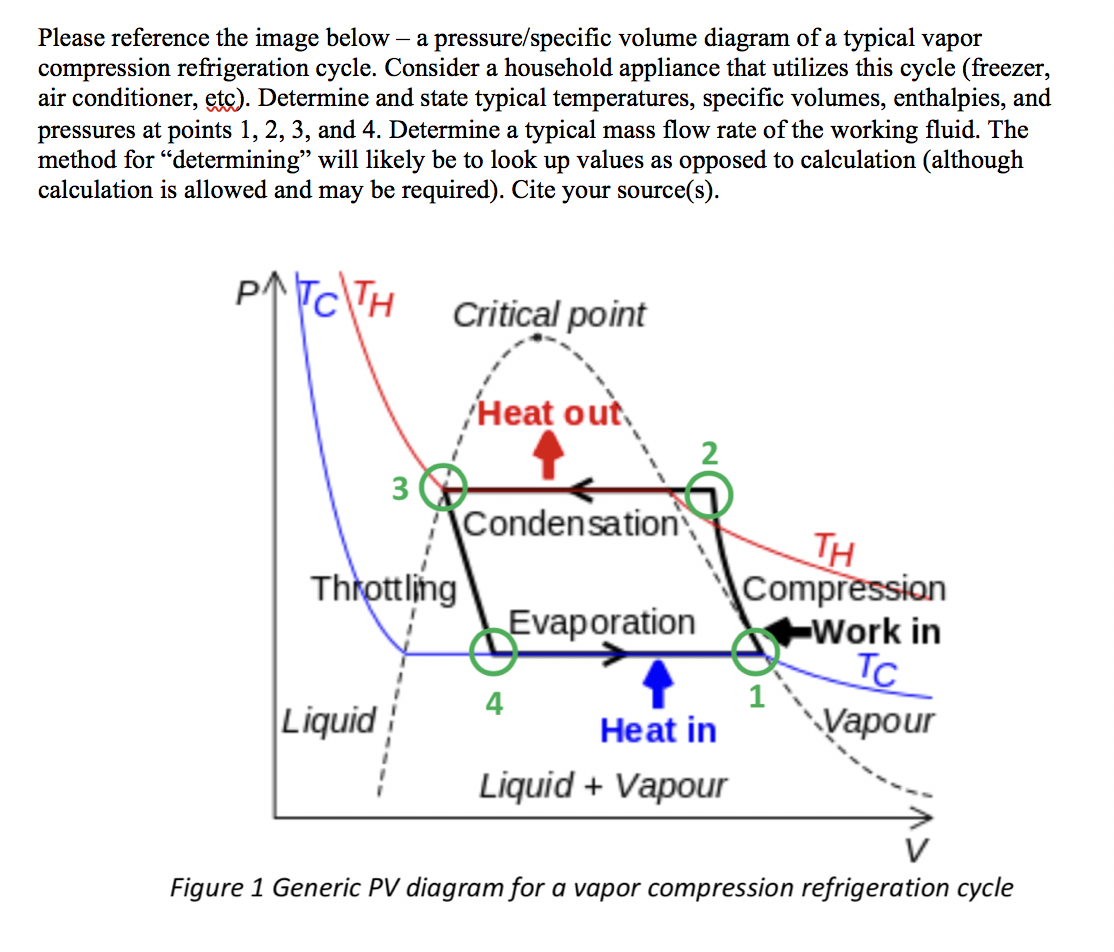
Solved Please reference the image below – a | Chegg.com

Design of Vapor-Compression Refrigeration Cycles

6. Vapor compression Cycle

Ch10, Lesson B, Page 3 - COP: Ideal Vapor-Compression Refrigeration Cycles

Explain with neat sketch the Vapor Compression Refrigeration system. Also  draw p-h and T-s diagram for the same.
Explain with neat sketch the Vapor Compression Refrigeration system. Also draw p-h and T-s diagram for the same.

Vapor-compression refrigeration - Wikipedia

Figure 1 from Investigation of R152a/R22 mixture in air conditioning system  | Semantic Scholar
Figure 1 from Investigation of R152a/R22 mixture in air conditioning system | Semantic Scholar